
Assignment for this week is, learn to analyze and understand data sheet of a microcontroller (in my case I am using Atmel ATtiny44A) And program the replicated "hello world board" with the LED and a SWITCH (Show the replicated hello world board in my week six )
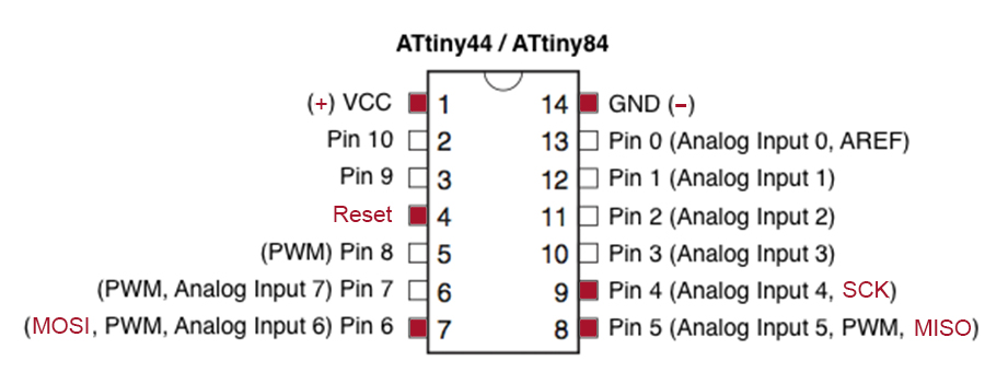
I began by looking through the Ttiny44 microcontroller's datasheet and trying to comprehend what the Attiny44's datasheet is about; it was an annoying in the beginning. The most interesting thing in the whole datasheet is the association of the pins to their coding representative numbers. The datasheet is also telling you where you can place components if there are special "needs" (for example analog input)
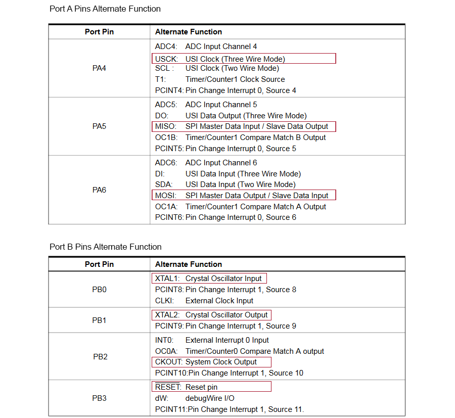
pins configurations
There I found the necessary information on the pins that I needed later on when programming
 "
"
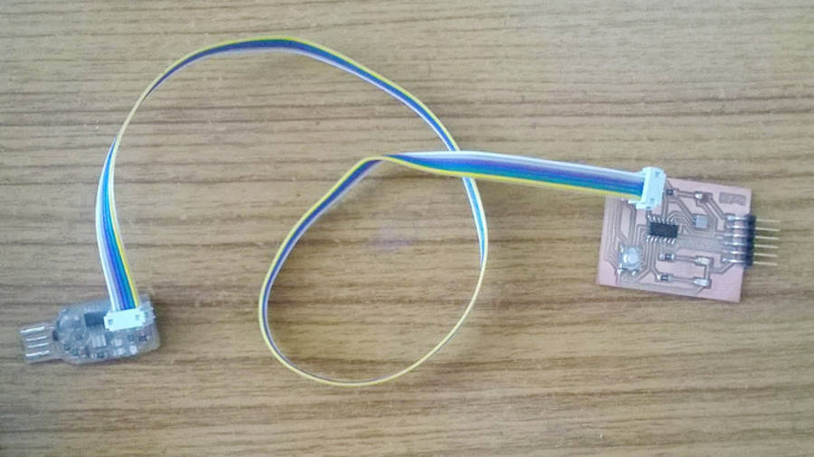
For Six -Wire ISP Programming of ATtiny 44 using six pins shown in below
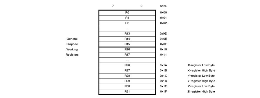
Memory is an area where code and instructions are stored.There are normally 3 types of memory present in a microcontroller. These are SRAM, FLASH, and EEPROM memories.

Registers are small memory elements in microcontrollers with 8 bits capacity. Registers can be accessed quickly by the ALU (Arithmetic and Logic Unit) of microcontrollers
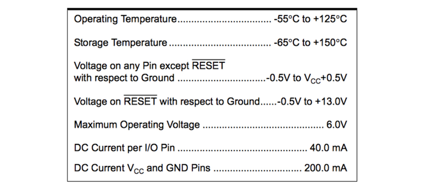
Other useful information
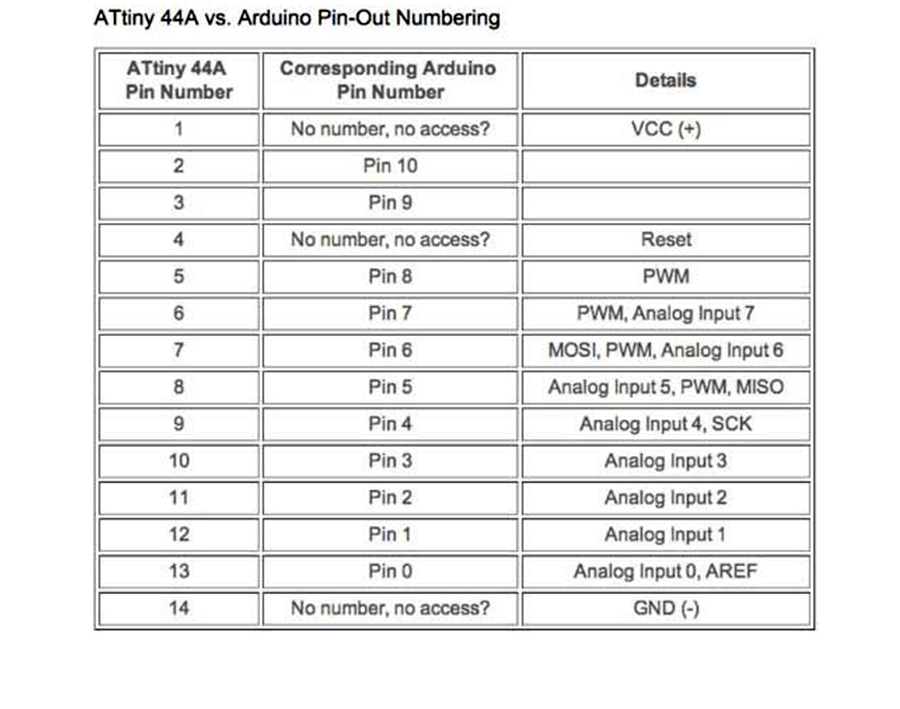
I thought that the Attiny pin and arduino pin was the same ,and recognized it NOT!.
In this week I am using Arduino IDE to program the Attiny44, so I compare Attiny44 pins with Arduino pins
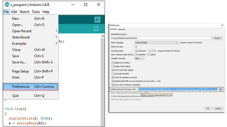
How to installing ATtiny support in Arduino ?
ATtiny can program in different methods. in this week I am using ATtin44. So I first studied about how to program ATtiny using Arduino IDE
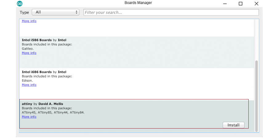
Close the boards manager. You should now see an entry for ATtiny in the "Tools > Board" menu
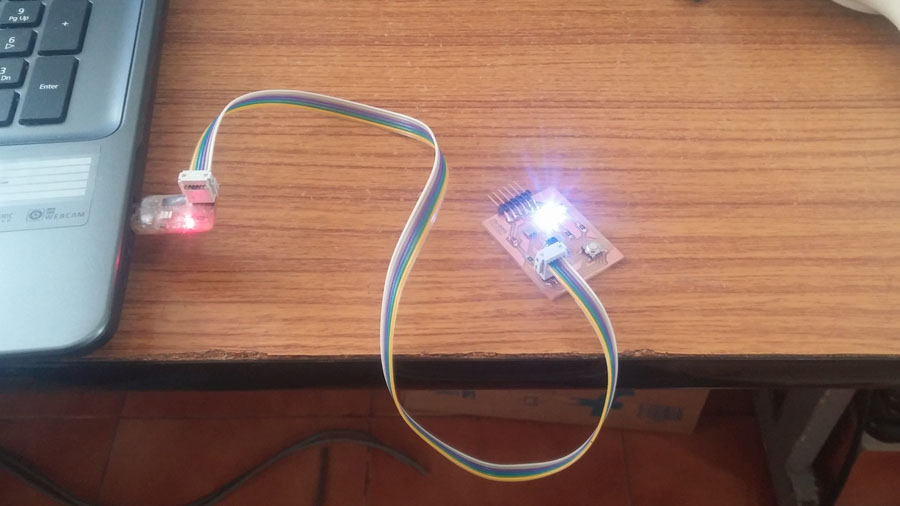
First, I installed all software and configure drivers for program the hello world board, then I connected fabISP to my computer using the USB cable and then connected my hello world board to the Fab
An AVR microcontroller you just bought will not work on your Arduino. It needs to be the bootloader for Arduino IDE
The tutorial explains how to do it on your ATtiny44A.
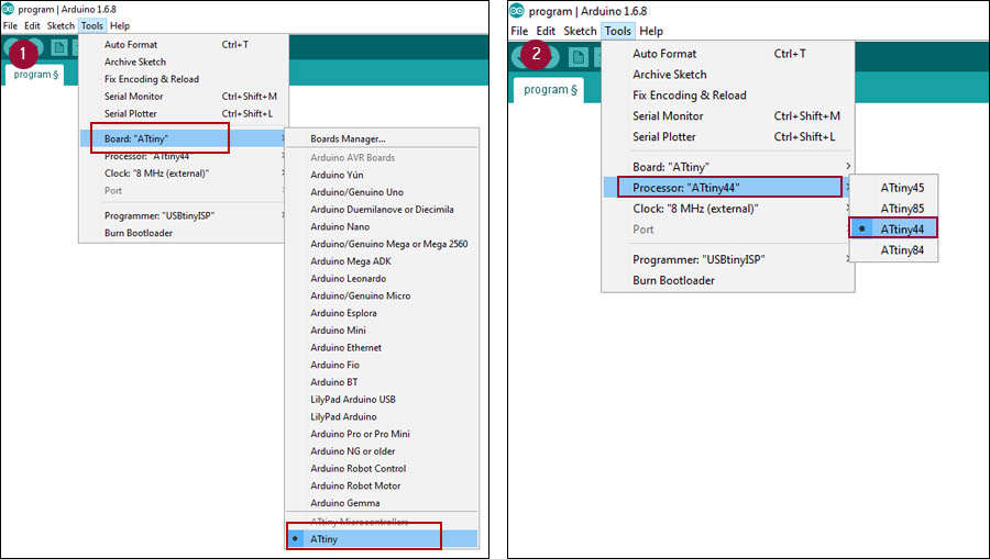
On the Arduino IDE, First, I select board type as ATtiny. Then selected microcontroller used on my board (in my case ATtiny44).
Here no need to selected port at serial port (port is automatically select ), this indicate port of PC to communicate with a microcontroller on the board.
Then Make the following changes in Tools menu
Board > ATtiny
Processor > ATtiny44
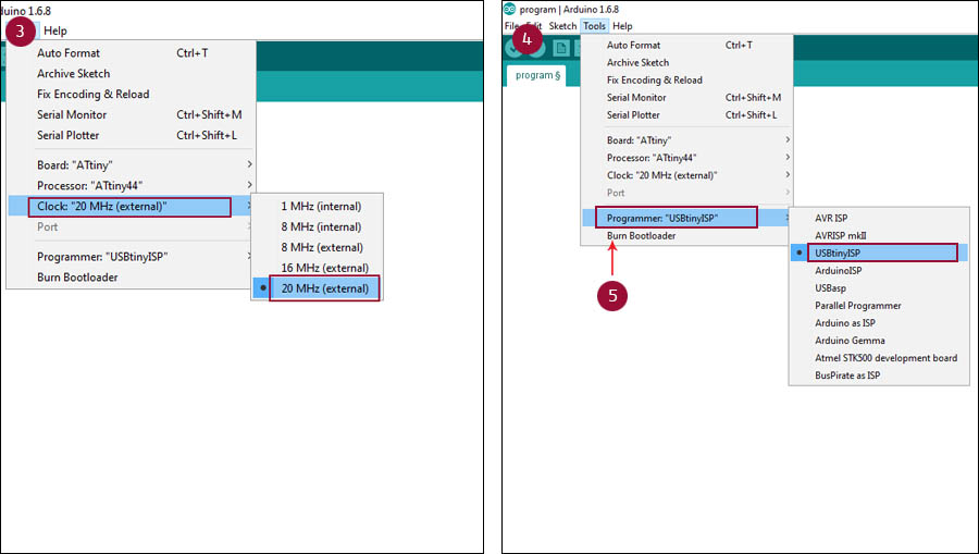
Clock > 20 MHZ(because i am using 20 MHZ Resonator in my Board)
Then i selected "USBtinyISP" at Programer. Then Programmer the bootloader to the board
For checking the board , I opened the blink example sketch and made some changes on pin (change pin number 13 to 2) configuration and then compiled it then loaded to my circuit board
For reference, use schematics and layout of board from week 6
void setup() {
// initialize digital pin 2 as an output.
pinMode(2, OUTPUT);
}
// the loop function runs over and over again forever
void loop() {
digitalWrite(2, HIGH); // turn the LED on (HIGH is the voltage level)
delay(1000); // wait for a second
digitalWrite(2, LOW); // turn the LED off by making the voltage LOW
delay(1000); // wait for a second
}
it worked just fine
I wrote a code for control two LED with one button using Arduino IDE.
int switchPin = 7; // switch is connected to pin 7
int led1Pin = 2;
int led2pin = 3;
int val; // variable for reading the pin status
int val2; // variable for reading the delayed status
int buttonState; // variable to hold the button state
int Mode = 0; // What mode is the light in?
void setup() {
pinMode(switchPin, INPUT); // Set the switch pin as input
pinMode(led1Pin, OUTPUT);
pinMode(led2pin, OUTPUT);
buttonState = digitalRead(switchPin); // read the initial state
}
void loop(){
val = digitalRead(switchPin); // read input value and store it in val
delay(10); // 10 milliseconds is a good amount of time
val2 = digitalRead(switchPin); // read the input again to check for bounces
if (val == val2) // make sure we got 2 consistant readings!
{
if (val != buttonState) // the button state has changed!
{
if (val == LOW) // check if the button is pressed
{
if (Mode == 0) {
Mode = 1;
} else {
if (Mode == 1) {
Mode = 2;
} else {
if (Mode == 2) {
Mode = 3;
} else {
if (Mode == 3) {
Mode = 0;
}
}
}
}
}
}
buttonState = val; // save the new state in our variable
}
// Now do whatever the lightMode indicates
if (Mode == 0) { // all-off
digitalWrite(led1Pin, LOW);
digitalWrite(led2pin, LOW);
}
if (Mode == 1) {
digitalWrite(led1Pin, HIGH);
digitalWrite(led2pin, LOW);
}
if (Mode == 2) {
digitalWrite(led1Pin, LOW);
digitalWrite(led2pin, HIGH);
}
if (Mode == 3) {
digitalWrite(led1Pin, HIGH);
digitalWrite(led2pin, HIGH);
}
}
Final result show in video
I don't have previous experience with Assembly programming; now I start to learn the Assembly .I got this from a nice and helpfull tutorial for those who are familiar with C,